Prepare a Rhino Model
CityComfort+ accepts 3D geometries created in Rhino or imported from other modeling platforms. Make sure the model units are consistent and the Y-axis in Rhino points to the north. All surface normal directions should always point outwards (Use the ‘Dir’ command to display and edit an object’s normal direction). CityComfort+ simulation depend on material properties and it is essential to organize your 3D model in layers described below:
Obj [Building/Ground/Tree]
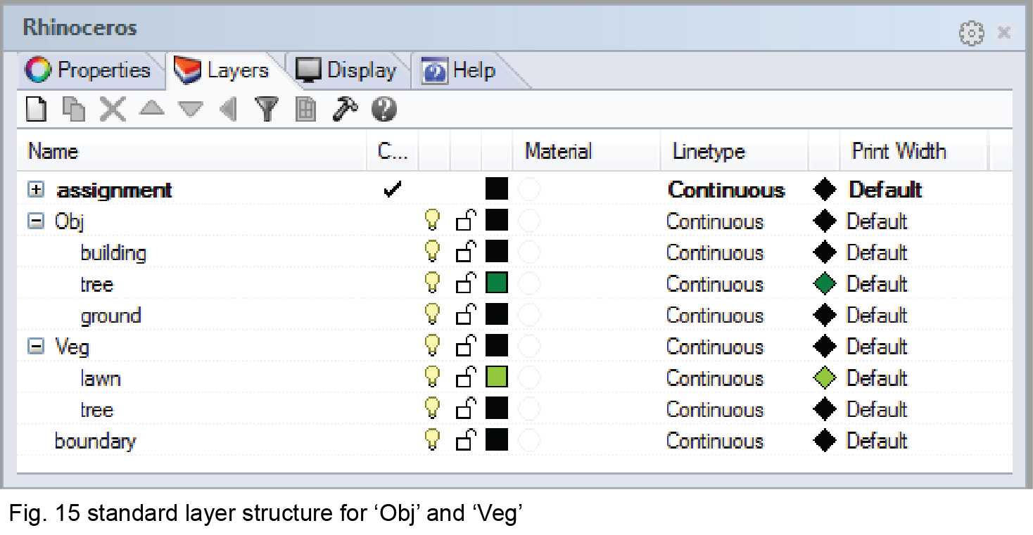
The ‘Obj’ layer contains 3D objects such as buildings, trees, and ground surfaces that participate in ray-tracing calculation. You need to create 3D objects under sub-layers for each distinct category. For example, if you have both brick and concrete buildings in your model, then two sub-layers needs to be created under Obj (e.g. building_concrete, building_brick). An example of Obj layer group is provided in Fig. 15.

Veg [lawn/Tree]
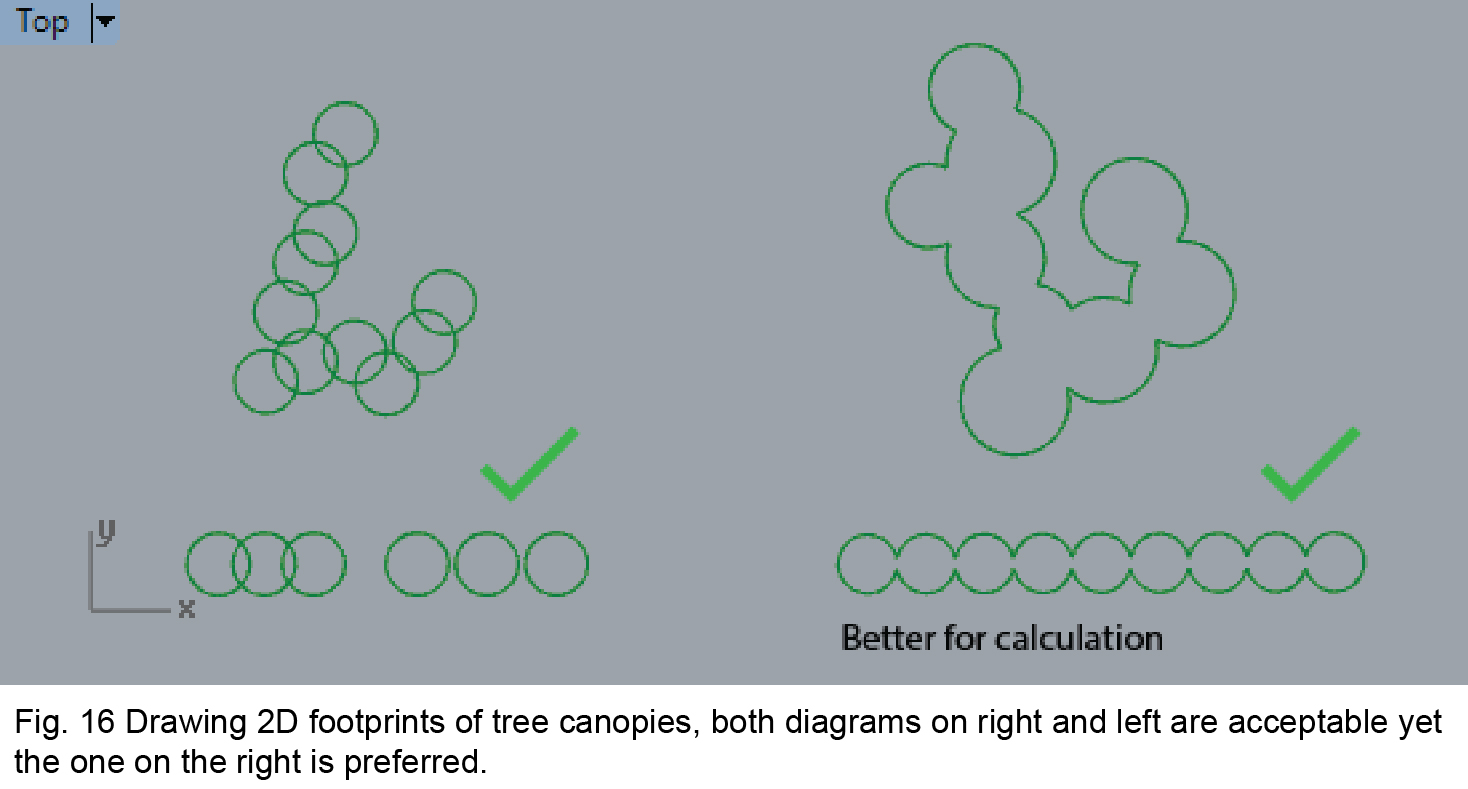
The Veg layer group contains 2D objects to describe footprints of tree canopies and lawns. Again, both should be placed under sub-layers and you should create enclosed lines, polyline or curves at the ground level (Fig. 15). If tree canopies are touching each other, please draw their footprints in continuous shapes together rather than separate footprints for each tree in order to make the simulation run faster. An example is provided in Fig. 16.
Hints: You can use the Rhino command of ‘Make2D’ to conveniently create 2D footprints. Even if you do not have any trees or lawns in your Rhino model, you still need to create the void Veg Group and sub-layers. This is because CityComfort+ needs these properties to compute heat island effects.

Analysis Boundary
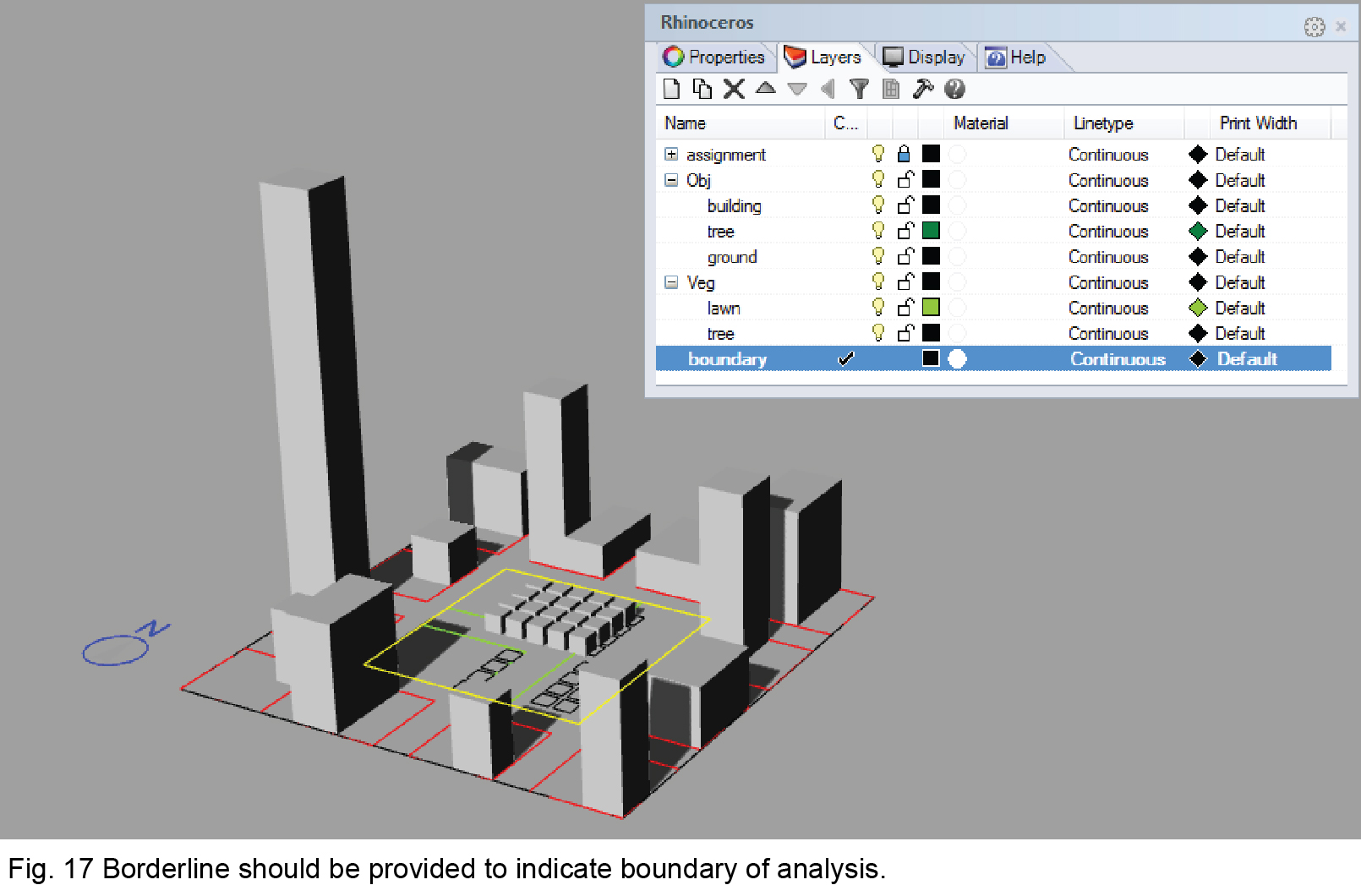
You need to create a borderline to inform CityComfort+ of the boundary of analysis. The borderline needs to be drawn in enclosed rectangles, polylines or curves and placed under the layer ‘boundary’ that is unlocked. An example is given in Fig. 17. Please don’t place other irrelevant objects in the ‘boundary’ layer.

System Layers
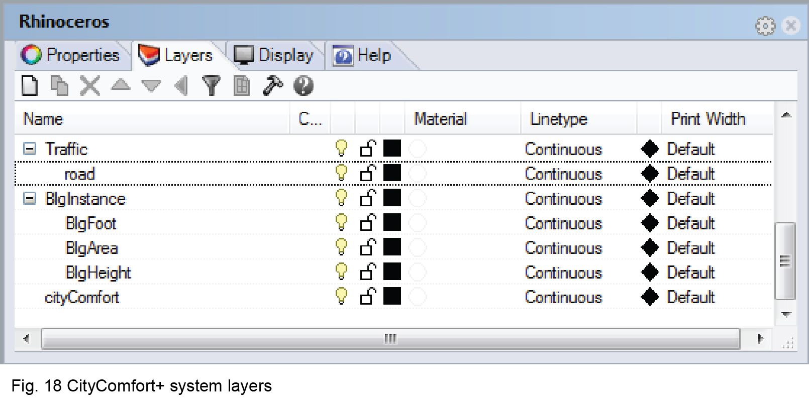
CityComfort+ will automatically generate system layers for calculation after each new project is created. These layers include ‘Traffic’, ‘BlgInstance’ and ‘cityComfort’ shown in Fig. 18.

- Layer ‘Traffic’ is useful for traffic related anthropogenic heat sources or air pollution. This function is still under development.
- Layer ‘BlgInstance’ and its sub-layer ‘BlgFoot’, ‘BlgArea’ and ‘BlgHeight’ are used to store the buildings information.
- Layer ‘cityComfort’ contains information and create sublayers while you are setting up the analysis scenario.
